The second receiver circuit we will study uses more components to do exactly the same job but it may have better sensitivity due to the inclusion of one extra stage of amplification and the use of a higher rail voltage. The higher rail voltage gives some stages a higher gain due to the higher amplitude of the signal. But some of the gain has been lost in the diode pump as this type of pump requires more energy to charge the 10u than a 0.47u. The use of a center-tapped voltage source saves two transistors in the bridge network but necessitates the use of a double-pole switch to disconnect both halves of the supply. A 27MHz receiver using a split supply
 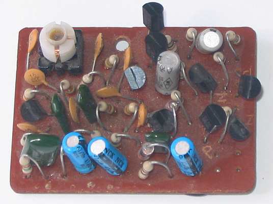 The 27MHz receiver PC board
Source: http://talkingelectronics.com


0 comments:
Post a Comment