
The signal from the transmitter is picked up by the receiver as bursts of tone between hash. Viewing the signal on a CRO (Cathode Ray Oscilloscope) will look something like fig: 23.
 The signal from the multi-channel transmitter will consist
of a regular waveform between background hash.
The receiver is required to pick out the signal from the noise and it does this by a process called integration and differentiation where the signal is detected due to its regular nature and this is used to charge a capacitor.
Another circuit determines the length of time the tone is present and these are combined to determine the nature of the control signal. Most of the circuitry for doing this is locked inside the chip in the receiver and the only components we can see are the external items on pins 10, 1 and 19. These determine the frequency detected by the chip and the length of the "highs," but all the rest of the signal processing is done inside the chip. The chip detects the waveforms shown in figs 14 - 19 and turns on the appropriate outputs.
 A multi-channel 2MHz receiver
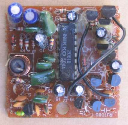 The 27MHz receiver PC board
Two outputs drive the motor in the forward/reverse direction and 4 outputs drive the transistors for the steering motor. The steering motor is simply a rotary actuator. This is similar to the armature of a motor, positioned inside a circular magnet.
The armature does not need brushes as it will only turn about 45° in one direction and 45° in the opposite direction, depending on the direction of the current. The output of the shaft will be connected to a lever to steer the front wheels.
The chip controls the two diagonally opposite transistors for the clockwise and anticlockwise rotation to get left and right steering. All the rest of the circuit has been previously discussed and the only new feature is the tapping at 4.5v for the motor. A diode on the 4.5v rail drops the voltage to 3.8v and the two output transistors drop a further 1v, so that motor receives about 2.8 to 3v.
Here are some remote control items, shown on the web, by a hobbyist who disassembles devices and makes a new project:
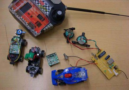 Some of these components were used to build a project and presented on the web.
Source: http://talkingelectronics.com


0 comments:
Post a Comment