
The next circuit is a 2 channel transmitter.
This circuit does not use a crystal but has a clever feature of using the two push buttons to turn the circuit on when it is required to transmit.
Click HERE for RX-3 IC datasheet .pdf
We have already discussed the operation of a circuit such as this, with a multivibrator and RF oscillator. The only new feature is the arrangement for producing two different tones.
The receiver requires a 1kHz and 250Hz tone for the forward and reverse outputs. The frequency of the multivibrator is determined by the value of resistance on the base of each transistor. The multivibrator is driven directly from the supply with the forward button and via a 150k for the reverse frequency.
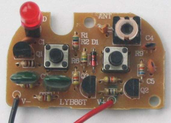
2 Channel Transmitter PC board
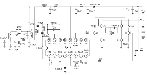
Circuit for the RX-3 IC
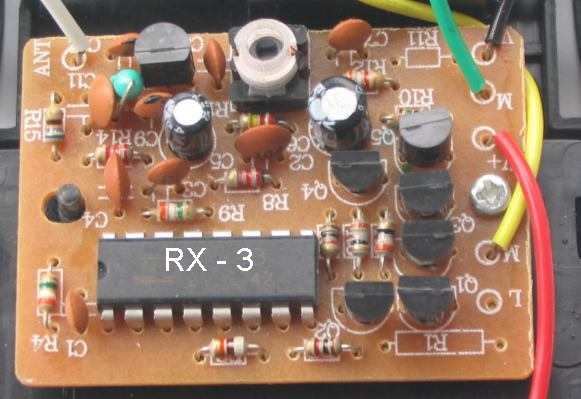
The circuit for the receiver has not been taken off the printed circuit board, however a general circuit is provided in the datasheet for the IC and this has been reproduced above.
Both output of the chip cannot be HIGH at the same time as this will destroy the transistors in the "H-bridge."
For the forward direction, the forward output is HIGH and this turns on Q9, Q11 and Q13.
For the reverse direction, the backward output is HIGH and this turns on Q8, Q10 and Q12.
This toy remote control car cost less than $8.00, but a defect in the design was noted.
The motor would reverse approx every 2 minutes for a short period of time, even though no transmitter button was pressed and the motor would operate in bursts when the car was distant from the transmitter. The interference was not from any electronic device in the home as the receiver was taken to an open space and it still faulted. The first transistor was removed and the fault did not occur. This means the RF transistor is generating a fault that is detected by the chip to turn on an output.
This could be due to the chip detecting a frequency of 1kHz or 250Hz to turn on an output. Random noise could be in this range and that's why the RX-3 receiver chip is unreliable.
Maybe that's why the car was $8.00!
Another point of comparison: the RX-3 receiver circuit consumed 4.4mA at 4.5v, while the RX-2B receiver consumed 0.7mA at 3v.
Source: http://talkingelectronics.com


0 comments:
Post a Comment